Changing circuit
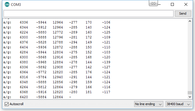
Revelation: MPU 6050 does not churn out analog data at all.
It PWMs its information using two pins out to the Arduino.
This changes quite a bit.
Should still be able to multiplex the data sent though.
Revelation: MPU 6050 does not churn out analog data at all.
It PWMs its information using two pins out to the Arduino.
This changes quite a bit.
Should still be able to multiplex the data sent though.
These may be a cheaper alternative, and will work when calibrated for a single user.
However varying finger sizes in width will apply different amounts of stretch tension to the material, resulting in inconsistent measurements for different users.
One could argue that a calibration could be saved for each and every user.
This is true but quite honestly people will not and cannot be bothered to do this and will be turned off quite significantly by the idea of having to spend even a few seconds calibrating and selecting their own settings every time they want to use the device.
Surveys sent out to people will prove rather contradictory as people will say that “They wouldn’t mind calibrating the device if it meant more accuracy and less power consumption” – as it is a conscious thought process that people will not want to come off as innately lazy and unwilling to go through a simple calibration process until you ask them to be brutally honest (which at that point is like trying to force them to answer in your favour).
At this point I have returned to using the idea of multiple accelerometers.
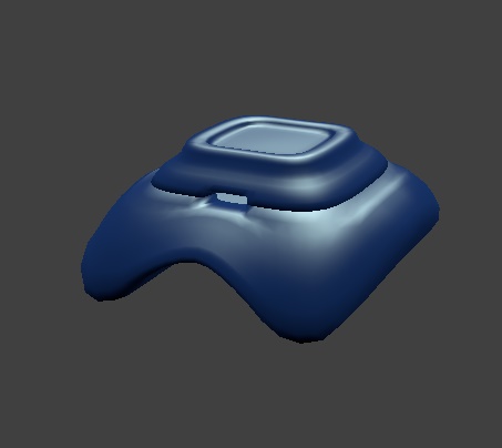
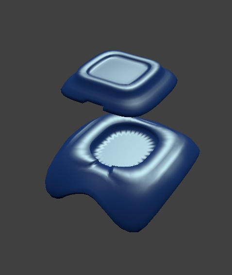
Accelerometers will be placed in the in the indent in the top half, with the vibration motors in the bottom half, as close to the fingers as possible to provide the strongest feedback possible.
The circuitboards will be glued in place and a sheet of neoprene will be placed in between the two halves to separate the two circuitboards to prevent any short circuiting, and the two halves glued together using some sort of adhesive.

Researching into viable options for wireless transceiving
Flex sensors are too expensive.
Decided on multiplexing several accelerometers.
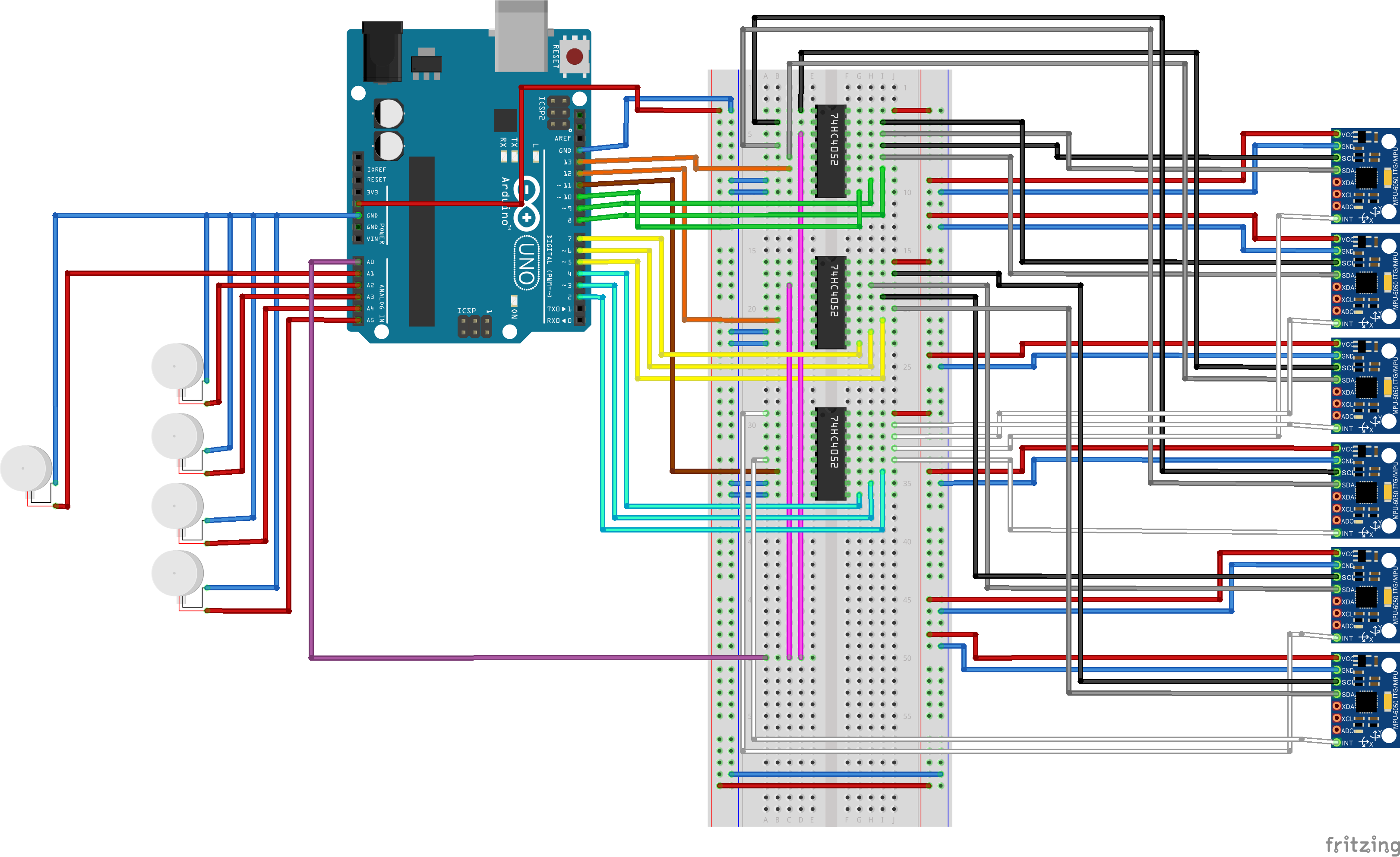
Circuit diagram and casing for each of the vibration motors and accelerometers to follow.
Accelerometers being used are:
MPU-6050
Testing will commence on one glove with just 2 accelerometers to begin with,
8 channel multiplexers will be used for multiple analog signals.
MPU-6050 throws out two analog signals, so two channels will be required for each accelerometer we use.
5 Analog pins will be set to output and used to individually controi the strength of the vibration motors up to 5V.
Success:
Batteries of any weight are easily ignorable when placed on the back of the wrist and or hand.
Problem 1:
Brand new factory produced gloves required significant bending stress applied for an extended period of time to the knuckle before any electronics are put inside.
Solution:
Machine is designed to fold and squash gloves / Buy capacitive bend sensors -> Research into price.
Problem 2:
The cheap motor vibrators take a split second amount of time to reach maximum output.
Solution:
Invest in more responsive but lower frequency motor vibrators / Introduce capacitance to the circuitry that builds up extra voltage.
Problem 3:
Wires are uncomfortable when they stick into the glove.
Solution:
Use ribbon cable and 3D print a container that fits the back of the hand comfortably.
Problem 4:
The motor vibrator wires are very fragile and tend to break and fray easily, which would not be ideal for something that is used in a glove
Solution:
Solder and mount the vibrator to a small circuitboard and hotglue the wires down to prevent any movement. 3D print an ergonomic case to house the vibrator in.
