Physical Computing – Final project Report
ImpactVR Gloves
Members: Jing Tan, Damian Hon
Introduction
Set up the project. Tell us the story of why you are doing what you are doing. What are you investigating? What inspired you? What is the social context your project operates within?
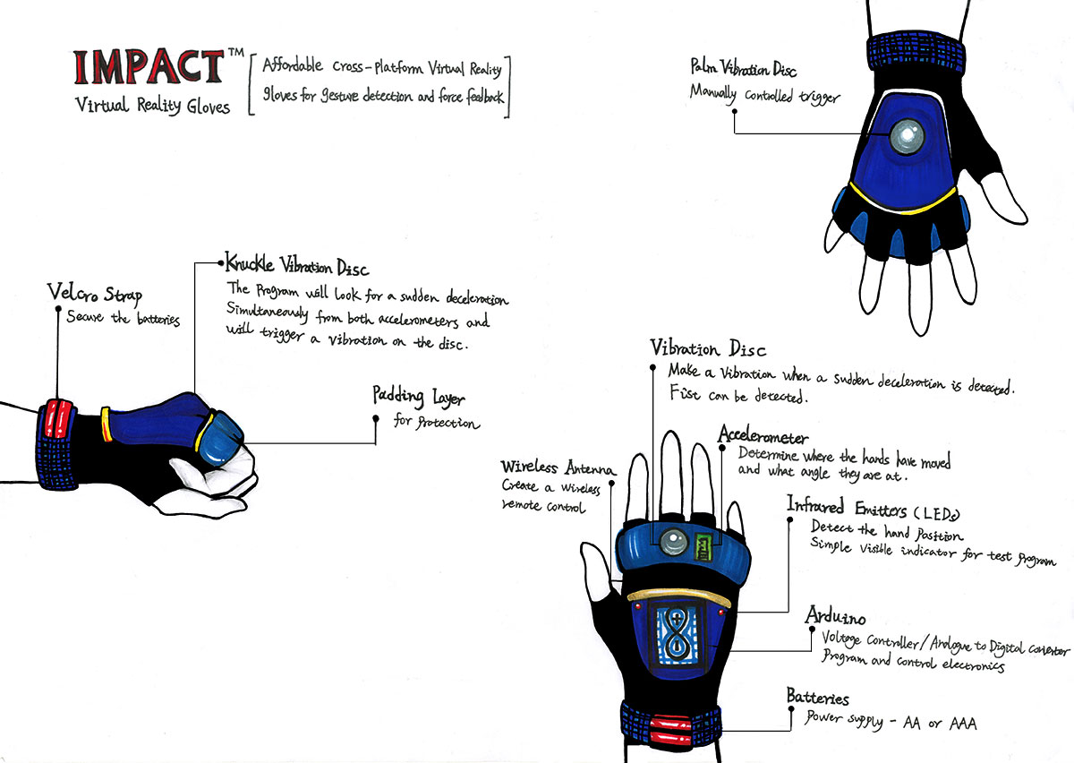
The aim of our project is to create a low-cost solution for gesture detection gloves which provides haptic feedback in games, simulations, virtual reality environments and walkthroughs depending on the software. The gloves can be used in an intuitive way with minimal calibration and they are easy to take on and off.
Traditionally, gesture detection gloves with haptic feedback have only been available at a high cost. In the current market, there are some high-end solutions which provide a sophisticated simulation of the sense of touch, such as Gloveone(1), The Peregrine Glove(2), Control VR(3) and Intel iQ(4). However, they are too expensive, requires too much calibration and are difficult to take on and off. We aim to develop a natural input/output device which is affordable and accessible for the general market, not just hardcore gamers.
Project Aims & Outcomes
A 200-300 word write up detailing your objectives
We will design and implement a glove input/output system to be used in applications based on hand gestures. Different designs will be tested and presented as prototypes – there will be a wired prototype and a wireless prototype of the glove. Once we get the wired prototype working, we will use a pair of XBee transceivers with a XBee Explorer to add wireless functionality.
The main project aims and outcomes with this project are:
- Detect hand position in 3D space and recognise gestures accurately using a DCcduino, accelerometers or flex sensors.
- Writing all of the sensor data to a serial connection.
- Use wireless transmission to remove any unnecessary wires. This will increase latency in terms of data transmission but still remain under a few milliseconds.
- Provide realistic haptic feedback in the form of multiple vibrating motors which are attached to different parts of the glove, upon meeting certain requirements dictated by the sensors and conditions that are dictated by compatible software.
- Inexpensive to produce and manufacture. We aim to keep the production cost for the final product under $30. The wireless prototype using XBee technology will be more expensive but should still be under $50.
- Stylish – the final product must be lightweight, look and feel like a pair of sparring gloves.
I/Os
Inputs
- MPU6050 accelerometers for hand gesture input: these accelerometers has built-in gyroscopes which can be used to detect hand position in 3D space. We’re using one for back of the hand.
- ADXL335 accelerometers: these accelerometers detect the change in tilt and gravity. We’re using one for each finger apart from the thumb.
Outputs
- Vibration discs for providing haptic feedback.
- LEDs: displaying the program status to the user, changes colour depending on the hand position. Green is when you’re in the resting position, it turns blue when the hand is tilted to the right and red when the hand is tilted to the left.
- Graphical output from the test program in Unity / Processing
- Sound output from the test program in Unity / Processing
Planning
The first thing we did was a group discussion of what we want to build. As we are both interested in immersive gaming applications and haptic feedback devices, we decided that a gesture detection glove system would be the best area for us to explore for this project. Once we have established a clear set of goals, we created a project plan with a list of things that the project needs to deliver in order to meet those goals, then we ranked the goals’ priority based on urgency as well as importance. Having looked at each goal, we defined a series of tasks that need to be completed in order to accomplish each one.
As certain tasks need to be completed before others can begin, we divided the work into manageable sections: planning, scheduling, estimating, costs, documentation, software and hardware engineering. For each task, we determined the resources necessary and estimated the approximate time it will take to complete. We are sourcing the components from China to reduce the production cost.
To make sure everything is clearly communicated and easily shared, we meet in the lab on a weekly basis, working on interaction design, circuitry, software programming, physical construction and documentation. Outside of these meetings, we worked remotely via Skype and Google Docs. During the reading week, we set up a Physical Computing studio at home to continue working outside of college hours.
In order to work best as a team, we divided up the responsibilities to our individual strengths. I will be working on the software side in Arduino, Processing and Unity as well as documentation, multiplexing and sewing, while Damian will be working on the hardware side, circuitry and soldering. The design, programming plan and 3D printing is done together.
Components
We researched all the components that we would need, beginning with the wired prototype and then the wireless prototype. The following components are required for our project:
- Two pairs of Sparring Gloves: These should be made with stretching waterproof fabric which are absorbent and quick-drying. One pair will be used for the wired prototype and the other pair will be used for the wireless prototype.
- Ten Accelerometers(ADXL-335): A Three-axis accelerometer which is simple to use with the DCcduino board. We are using one for each finger in order to measure the change in tilt.
- Two Accelerometers(MPU-6050): combines a 3-axis accelerometer and a 3-axis gyroscope which can be used to detect position in 3D space. They are very useful for measuring the hand rotation around an axis and for measuring the speed of rotation. These are used for the back of the hand.
- Two Potentiometers: These are used for changing the calibration of the MPU-6050 accelerometers dynamically with the Calibration Program.
- Twelve Vibration discs: one disc will be attached for each finger and for each palm to provide force feedback.
- Two RGB LEDs: To provide visual feedback from the test program. The LEDs should change colour as the rotation of the user’s hand changes.
- Voltage Controller / Analogue to Digital Converter – We’re using a DCcduino Uno which is a popular Arduino Uno R3 pin and feature compatible clone.
- Three Batteries(Kodak Xtralife Alkaline AAA LR03 1.5V Battery) – Provides a long-lasting power source. These batteries can be easily replaced by the user.
- Two XBee Modules: We’re using the Series 1 models with a wire antenna. They send and receive data over a serial port and are compatible with both the computer and the DCcduino, which is ideal for our project.
- One Xbee Shield: This is used for the wireless prototype to interface with the DCcduino.
- One XBee Explorer Dongle v2: This acts as an interface between the computer and the XBee. They’re used as a backup option to configure the XBee and pass data to and from the computer.
- Various Wires: These are needed for the wired prototype and will be removed in the wireless prototype.
- Ribbon Cables: for making a lot of connections without a big mess of wires.
- One 16 channel analog Multiplexer(74HCT4067): Due to time and cost constraints we’re using a 16 channel multiplexer for one hand. 15 channels will be used to multiplex the accelerometers – 5 for the ADXL-335 accelerometers(X,Y,Z) and 1 for the MPU-6050 accelerometer.
Hardware & Electronic Engineering
To start with, we ordered two pairs of sparring gloves from China for experimenting with different set-ups. Testing commenced on one glove with just one accelerometer to begin with.
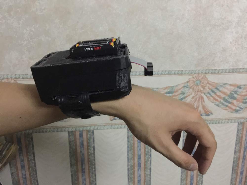
Trying to use generic parts which are affordable means we really need to design the project well, making sure everything fits and will work together. When designing the hardware aspects of the system, it was important to keep both its functions and aesthetics in mind. We want the end product to be lightweight, ergonomic and have the look of sparring gloves. At first, we were concerned about the weight of batteries, however during user testing we found out that the batteries of any weight are easily ignorable when placed on the back of the wrist and or hand.
The brand new factory produced gloves required significant bending stress applied for an extended period of time to the knuckle before any electronics are put inside. We had to bend them manually, a potential solution for the final product could be using machine to fold and squash gloves.
Knowing that the wires would cause discomfort to the user when they stick into the glove, we planned some custom options for ergonomic housing. Ribbon cables were used and a container that fits the back of the hand comfortably is modelled in Blender, it’s printed using a MakerBot Replicator 3D Printer.
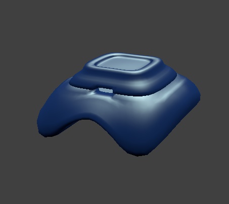
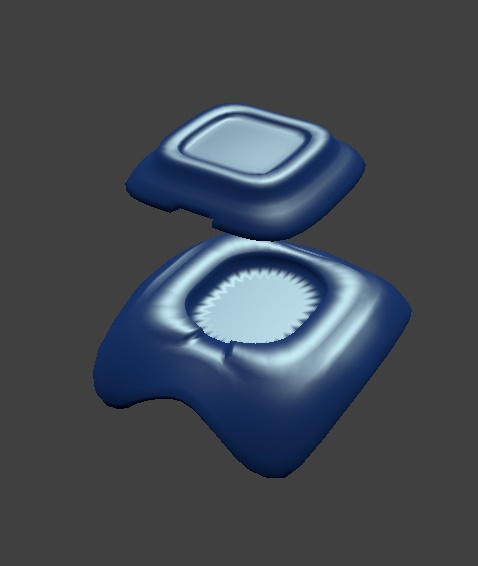
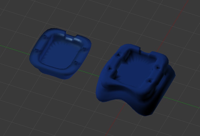
The wires of the vibration discs are very fragile and tend to break and fray easily, which would not be ideal for using in a glove. To solve this problem, we decided to model and 3D print an ergonomic case to house the vibrator discs in. The vibration discs will be soldered and mounted to a small circuit board, the wires will be glued down to prevent any movement. The circuit boards will be glued in place and a sheet of neoprene will be placed in between the two halves to separate the two circuit boards to prevent any short circuiting, the two halves will be glued together using superglue. Accelerometers will be placed in the in the indent in the top half, with the vibration motors in the bottom half, as close to the fingers as possible to provide the strongest feedback possible. Holes are added to the base of the case for an easy and safer fastening method.
The design process consists of defining the project aims, exploring the different alternatives for reaching the desirable outcome and choosing a plan to follow. We researched alternative options to using accelerometers, such as bend sensing materials, conductive lycra and bend flex sensors which could allow us to do extra gesture detection. However, varying finger sizes in width will apply different amounts of stretch tension to the material, resulting in inconsistent measurements for different users. The flex sensors are too expensive. In the end, we decided to stick to the initial decision of combining multiple accelerometers.
A calibration could be saved for each user individually but it’s not an ideal solution, as people will be turned off by the idea of having to spend time calibrating and selecting their own settings every time they want to use the device.
Analog Devices(5) makes some good accelerometers, we chose to use the ADXL335 – a small, thin, low power 3-axis accelerometer to get 3D positioning, as two-axis accelerometer can only get two directions of movement. We used four accelerometers(one for each finger) to measure the change in tilt, speed of movement, acceleration and deceleration. This will give us a good measurement of the tilt of the hand. 1 with built-in gyroscope to detect position in 3D space. For the wireless modules we’ve been using as well as the I2C accelerometer, we’ve used header files that come from the companies that own the chips. These are used for the finger.
The plan was to add wireless functionality to our gloves after we’ve finished a working wired prototype. We researched how to send and receive data using wireless transmission, particularly how to send digital output signals using low-cost wireless modules. We chose XBee data modules which will provide a wireless data link with greater range and a faster data speed than the basic wireless modules. The USB cable will be removed from the DCcduino and the board will be powered using an external supply such as a 9V battery or AAA batteries.
Since Xbees don’t require their own library, connecting the transceiver to an DCcduino was simple with a XBee shield. As a backup option, we bought an XBee Explorer dongle which enables wireless communication with a computer via USB.
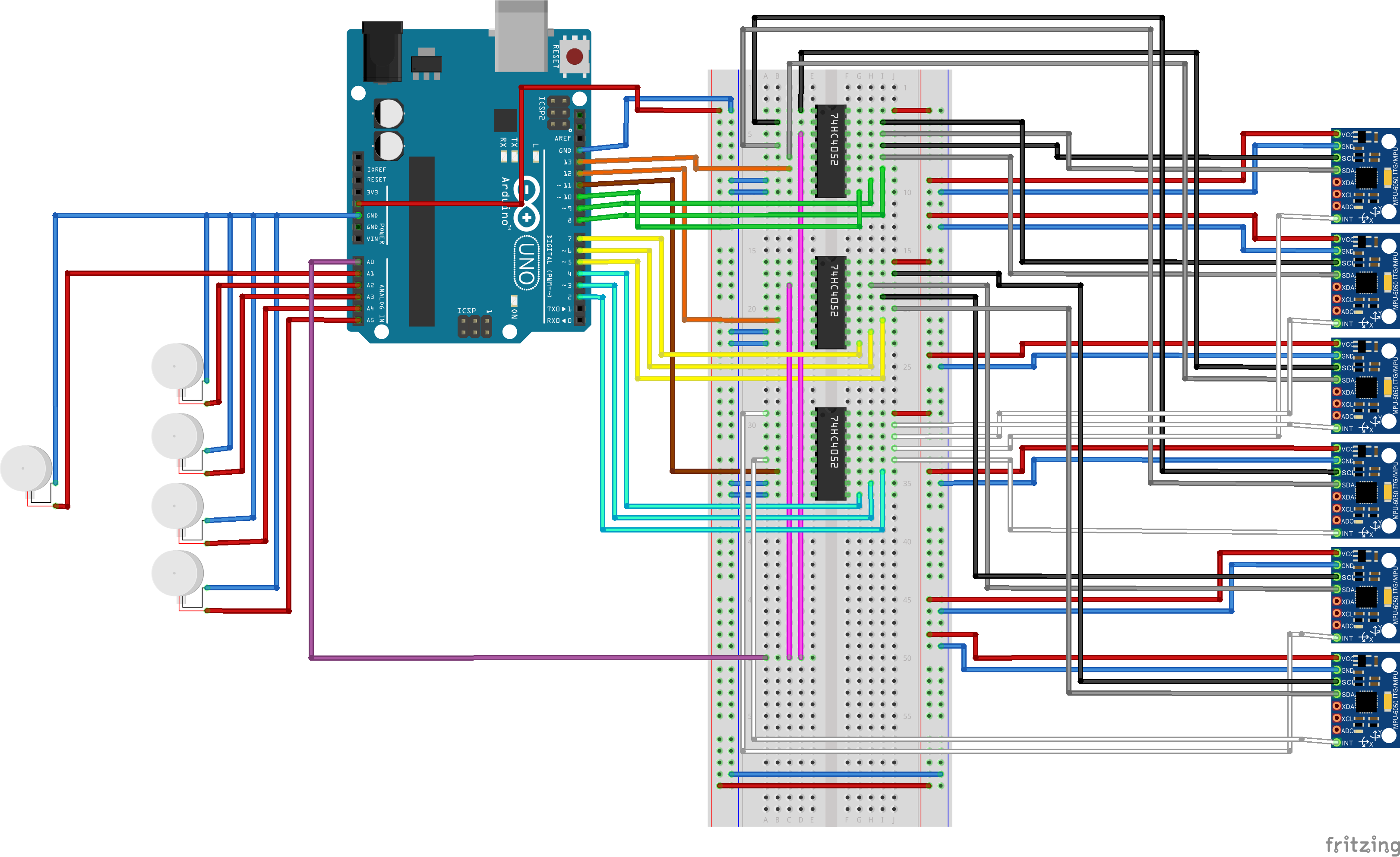
Schematic
Here’s the initial Fritzing circuit diagram of our hardware setup for prototyping a single glove:

Programming Plans
What challenges did you overcome?
Before any programming can begin, we had an end result in mind and designed a systematic plan, beginning with the most minimum functionality and then expanding its features. With wireless communication, we wanted to make sure that the data can be exchanged successfully over a wire first, then change the hardware.
Step One: Get one accelerometer to work with DCcduino.
Step Two: Get two accelerometer to work with DCcduino.
Step Three: multiplex the accelerometers.
Step Four: Add wireless transmissions.
Step Five: Output to the vibration discs.
Step Six: Programming custom software in Processing for giving visual output.
Planned Schedule:
Week One: Timing, Plan
Week Two: Design, Schematics
Week Three: Hardware engineering, 3D modeling
Week Four: Software Development, Testing, 3D printing
Week Five: Finish the Wired Prototype
Final Build: Finish the Wireless Prototype
ADXL335 Accelerometer
The program reads the analog input value and map it to the range of the analog output values using the map() function. It changes the analog output value and print the results to the serial monitor.
MPU6050 Accelerometer
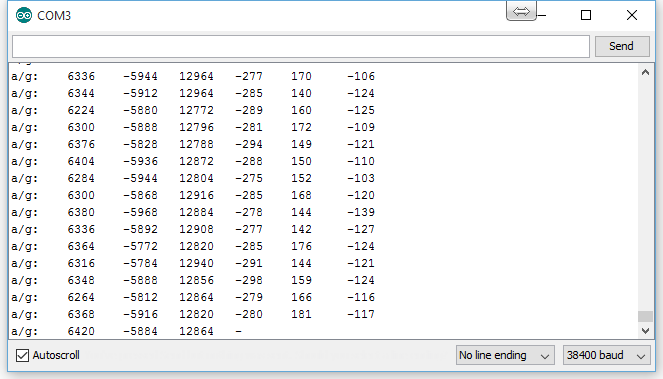
The program reads the raw values for the accelerometer and gyroscope, initialises serial communication for Processing output, viewing the 3D representation of the data from the accelerometer and checking for FIFO overflow. We based our code on Jeff Rowberg’s I2C lib(6).
74HC4067 Multiplexer
The program controls the pins output table in an array which holds incoming values from the multiplexer. A function void setPin(int outputPin) is used to select pin on the multiplexer. The captured data is dumped from the array to the serial monitor.
For the wireless modules and the I2C accelerometer, we’ve used header files and the data sheets that come from the companies that own the chips as a starting point(reference).
Challenge: DCcduino was not recognised by computer as a board.
Solution: We had to install the DCcduino Uno driver to make the computer recognize this device over USB. Once we’ve done this, we were able to plug in the board and select the new COM in the Arduino IDE Serial Port menu and upload code.
Challenge: Getting FIFO Overflows and intermittent crashing when testing two MPU6050 Accelerometers with Arduino(There were no issues when testing with just one accelerometer).
Solution: Testing the glove with a range of different gestures to find out what makes it crash. Making sure that the baud rates are the same in the Arduino .ino file and the Processing pde file.
Uncommenting the line “OUTPUT_READABLE_YAWPITCHROLL” to see the yaw/ pitch/roll angles (in degrees) calculated from the quaternions coming from the FIFO.
Disconnecting the interrupt pin stopped the FIFO overflows from happening. The program no longer crashes even when being left on for four hours. It’s very responsive and can tell if the hand is upside down.
Challenge: The sensor of the MPU6050 accelerometer is totally level but it thinks that it’s angled slightly. The offsets needs to be adjusted in order to counteract this error.
Solution: After researching on the I2Cdevlib forums, I found a useful library by Luis Rodenas(7) to automatically calculate MPU6050’s offsets.
Challenge: 3D printing and assembly of the ergonomic housing for the DCcduino, batteries, accelerometers and vibration discs
3D printing and assembly of the ergonomic housing for the DCcduino, batteries, accelerometers and vibration discs.
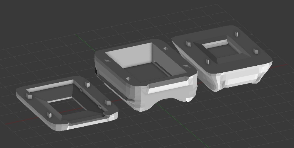
Solution: We had to print the cases multiple times to get the best results, as it was difficult to get the dimensions right and changes need to be made to the models – it had to be split it into certain sections to hold both batteries in the DCcduino.
The below image shows the design of the case for the accelerometers. A elastic band will be sewn to the glove through the hole on the side.

Here’s the design of the custom housing for the DCcduino and the AAA batteries with two layers. A stretchy wristband will go through the hole on the side and sewn to the wrist part of the glove:
Challenge: Running out of pins when managing multiple inputs / outputs. Need to multiplex the accelerometers and vibration discs.
Solution: Use 74HC4067 16-channel analog multiplexers and shift registers to expand the I/O capabilities of the DCcduino. Use port manipulation to control the digital pins which are connected to the 74HC4067’s control pins. This allows for much faster I/O control and reduces the amount of memory the sketch will use. I used the datasheet of the 74HC4067 multiplexer as a reference(8).
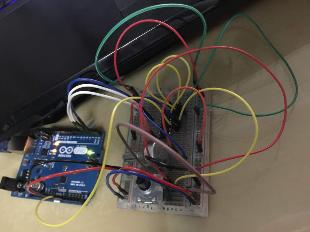
To start with, I’m testing two accelerometers with a 8-channel analog 74HC4051 multiplexer. However, I’m having problems with the values – when they are connected through the multiplexer, they give random readings.
I tried out different setups and tutorials as well as debugging by connecting unused channels to the ground, however I’m constantly having the same problems. I can’t find any existing solutions online and have tried asking for help from the Code Inn(9). It turned out that the culprit is the potentiometer, it started working after I used potentiometers with a different resistance value.
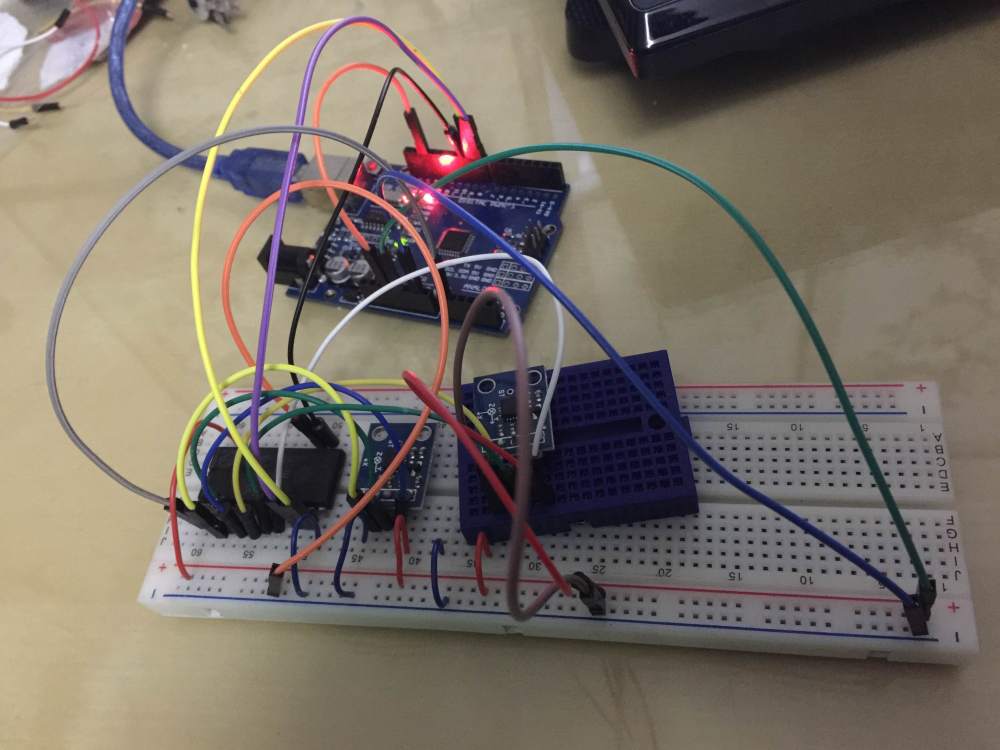
I moved on to multiplexing two accelerometers and was able to get correct values out after two attempts. I found out that it’s important to connect 3.3v to AREF for the best possible accuracy and precision.
Final Code
Any code used in the project must be zipped and included with the final pdf.
Conclusion
What are the future possibilities for this project?
Building this project, I have learned a great deal about electronics and programming. It would be ideal to include motion tracking and make the final product compatible with multiple consoles and devices, however we decided not to implement these features in our prototype due to time and budget constraints.
Another future possibility is to connect Arduino to Unity for immersive games with physical feedback, engaging players in interactive environments. Uniduino is a good starting point. I’m interested in exploring more functionalities instead of just rotating a 3D model in Unity based on input from accelerometers.
The cheap motor vibrators take a split second amount of time to reach maximum output. This can be improved by using more responsive but lower frequency motor vibrators or Introducing capacitance to the circuitry that builds up extra voltage.
Wekinator could be used for teaching the computer to recognise gestures and associate them with games/animations. to control interactive environments using gestures sensed from Arduino.
The 3D printed ergonomic housing for the Arduino makes the product more bulky than we would ideally like. To make it more lightweight, Arduino Mini could be used instead or we could build our own hardware.
Presentation
Video
The colour of the LED changes according to the input value from the accelerometer.
Spinning a 3D model on screen using XYZ axis input values from.an ADXL335 accelerometer. The values need to be tweaked as it’s very jittery.
References
- Gloveone: https://www.gloveonevr.com/
- The Peregrine Glove: http://theperegrine.com
- Control VR: https://www.kickstarter.com/projects/controlvr/control-vr-motion-capture-for-vr-animation-and-mor
- Intel iQ: http://iq.intel.co.uk/
- Analog Devices: http://www.analog.com
- Jeff Rowberg’s I2C lib: https://github.com/j…es/MPU6050_DMP6
- Luis Rodenas’ library to automatically calculate MPU6050 offsets: http://www.i2cdevlib.com/forums/topic/96-arduino-sketch-to-automatically-calculate-mpu6050-offsets/
- Tutorial on using the 74HC4067 16-Channel Analog Multiplexer: http://tronixstuff.com/2013/08/05/part-review-74hc4067-16-channel-analog-multiplexerdemultiplexer/
- The Code Inn’s tutorial on multiplexing: http://thecodeinn.blogspot.co.uk/2013/10/arduino-and-multiplexing.html